Rubber Engineering Tolerances
Engineering Tolerances
Specifying tolerances is a must in any manufacturing task. Tolerances communicates to a manufacturing company the limits they can reach for a part regarding dimensions or geometry. The lack of or misinterpreting of tolerances may well lead to an unusable part. This could result in delays and unnecessary additional costs and resources developing a new part.
What are engineering tolerances?
An engineering tolerance is the allowable amount of variation in a specific measurement from its base value, also known as the nominal value. Tolerances can be specified for any measurement (temperature, weight, volume, current, voltage, etc.) but tolerances specified in mechanical engineering generally apply to linear, angular and other physical dimensions that are found on a technical drawing.
No manufacturing process is perfect, every part that has ever been manufactured has had some amount of variation in its dimensions or geometry, even if it is slight. This will always be the case for example: a rubber D-section with a specified wall thickness of 10 mm will never be exactly that. It could end up 10.5 mm when extruded.
Differentiating Tolerances
Different industries work to different engineering tolerances. The 0.5 mm variation in the rubber D-section above might not seem significant, and it's not in the rubber extrusion industry, but a 0.5 mm variation in the aerospace industry is quite large meaning there is less margin for era. Therefore, it is important to understand the relevant tolerances of your industry and know how to apply them correctly.
Dimensional Tolerancing
Dimensional tolerances are the tolerances that govern the dimensions (size) of a given part (length, radius, angle, etc.). There is another, complimentary method of tolerancing which is Geometric Dimensioning and Tolerancing. This form of tolerancing governs the geometry (shape) of a given part (flatness, parallelism, symmetry, etc.).
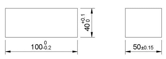
Nominal values are the specified dimensions for any given part. In the diagram below, the nominal values are: 40 mm, 50 mm, and 100 mm. If no tolerances are added, the actual dimensions on the final part will be completely dependent on, among other factors, the standard tolerances of the manufacturing company, machinery, and machinist capability.
What are the three different types of dimensional tolerances?
- Lower deviation - Communicates the smallest value a dimension can have on the final part. This is noted by the “-” sign next to the 100 mm dimension in the diagram below This means that the dimension can acceptably be as small as 99.8 mm but cannot be larger than 100 mm.
- Upper deviation - An upper deviation communicates the largest value a dimension can have on the final part. This is noted by the “+” sign next to the 40 mm dimension in the diagram below. This means that the dimension can acceptably be as large as 40.1 mm but cannot be smaller than 40 mm.
- Bilateral deviation - Communicates the total room for error that a dimension has on the final part. This is noted by the “±” sign next to the 50 mm dimension in the diagram below. This means that the dimension can acceptably be as small as 49.85 mm and as large as 50.15 mm.
A question that arises here is: “is there a difference between a nominal value of 99.5 mm with an upper deviation of +0.5 mm and, a nominal value of 100 mm with a lower deviation of -0.5 mm?”
The answer is yes.
The reason for this is that the manufacturer will strive for the dimension's nominal value. So, if the intention is for a part's dimension to be 95 mm, this should be specified as the nominal dimension, not 100 mm.
General Tolerances
When each of a part's dimensions follow the same class of tolerances, general tolerances will be applied. This can either be applied by adding a table to the technical drawing, as shown in the diagram below. You can also add a note saying: “ISO 2768-m” or “ISO 3302-E1”. The “-m” and “-E1” are the tolerance classes of “ISO 2768” and “ISO 3302” standards. The table below shows the E3 tolerance class of the ISO 3302 standard.
| Nominal Dimension (mm) | Tolerence, ± (mm) | |
|---|---|---|
| Greater than | Less than or equal to | |
| 0.00 | 1.50 | 0.40 |
| 1.50 | 2.50 | 0.50 |
| 2.50 | 4.00 | 0.70 |
| 4.00 | 6.30 | 0.80 |
| 6.30 | 10.00 | 1.00 |
| 10.00 | 16.00 | 1.30 |
| 16.00 | 25.00 | 1.60 |
| 25.00 | 40.00 | 2.00 |
| 40.00 | 63.00 | 2.50 |
| 63.00 | 100.00 | 3.20 |
| 100.00 | 3.20% | |
General tolerances can be applied to linear dimensions, angular dimensions, external radius, chamfer heights, etc. The ISO 2768 and ISO 3302 mentioned above are examples of commonly used general tolerances that have been specified by the International Standards Organisation. ISO 2768 is applied to machined parts and ISO 3302 is applied to rubber parts that have been extruded or moulded.
Types of fits and clearences
In engineering, a “Fit” refers to the clearance between two mating parts. The international standard ISO 286 provides a system of engineering fits which is used worldwide. The choice of fit depends on the application. There are two things that should be considered. “Is a fit needed that enables rotation of the parts?” or “Should there be zero movement between the parts?”.
- Clearance fit: Requires a shaft diameter to be smaller than that of the hole. This means there will always be a gap between the two. If the engineering solution needs the two to be able to slide or rotate independently of each other, this is the way to go. So, in this case both the shaft and the hole have tolerances that will ensure no overlapping.
- Transition fit: The maximum shaft size is bigger than the minimum size of the hole. At the same time, the minimum shaft size is also smaller than the maximum size of the hole. So, it is neither a clearance fit, nor an interference one. Depending on the final measurements, the tolerances allow for both scenarios to happen while not going into the extremes.
- Interference fit: The shaft diameter size is always bigger than the hole. Even when the shaft is at its minimum diameter and the hole at its largest. An interference fit ensures there is no movement between the two parts. Application of force is necessary during the physical fitting. Heating of the hole, freezing of the shaft and using a lubricant can all help to ease the process.
There are two systems to choose from: “Hole Basis” and “Shaft Basis”. The hole basis system takes the measurement of the hole thus determining the diameter of the shaft and achieving the required fit. The shaft basis system works in the opposite way.
Engineers tend to follow the hole basis system because of its simplicity. Drilling does not allow for much precision, as the tooling comes in certain measurements.
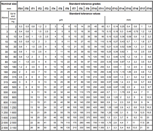
The table below shows, common notation for different fitting scenarios. Each notation pair corresponds to a set of dimensional tolerances for the hole and shaft being designed. An upper-case letter signifies the hole, a lower-case letter signifies the shaft, the actual letter itself signified the start point of the tolerance zone, and the accompanying number indicates the international tolerance (IT) grade.
| Type of Fit | Description | Hole Basis | Shaft Basis |
|---|---|---|---|
| Clearance Fits | Loose Running | H11/c11 | C11/h11 |
| Free Running | H9/d9 | D9/h9 | |
| Close Running | H8/f8 | F8/h8 | |
| Sliding | H7/g6 | G7/h6 | |
| Locational Clearance | H7/h6 | - | |
| Transition Fits | Similar | H7/k6 | K7/h6 |
| Fixed | H7/n6 | N7/h6 | |
| Interference Fits | Press | H7/p6 | P7/h6 |
| Driving | H7/s6 | S7/h6 | |
| Forced | H7/u6 | U7/h6 |
Say we want to design a hole and a shaft with nominal dimensions of 25 mm, and we want a sliding fit following the hole basis system. We would select the H7/g6 notation fro the table above. First, let's consider the H7 notation. The upper-case nature of the “H” means that we are dealing with the hole. The actual letter “H” indicates that the tolerance zone starts at a nominal value plus 0 µm, and the number 7 corresponds to the IT7 tolerance range in the diagram below which is 21 µm. So, we now know that the hole's actual dimensions can vary between 25.000 mm and 25.021 mm. If instead of H7 it were F7, the tolerance zone would start at a nominal value plus 20 µm, so the hole's actual dimensions would vary between 25.020 mm and 25.041 mm. Let's consider the g6 part of the notation. The lower-case nature of the “g” means that we are dealing with the shaft, the actual letter “g” indicates that the tolerance zone starts at a nominal value minus 7.µm, and the number 6 corresponds to the IT6 tolerance range which is 13 µm. So, we know that the shaft's actual dimensions will vary between 24.993 mm and 24.980 mm.
Geometric dimensioning and tolerancing (GD&T)
Additional to dimensional variations in every part ever manufactured, there are also geometric variations. GD&T is a universally standardised way to define tolerances for the geometry of manufactured parts.
The example in the diagram below shows how to define the parallelism of two surfaces.
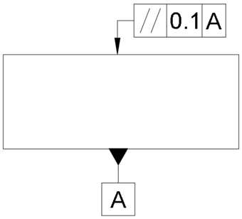
The symbol attached to the bottom surface known as the datum feature, sets that surface as the reference. The symbol attached to the top surface is the feature control frame and is divided into three boxes in this example. The first contains the parallelism geometric characteristic. The second shows the 0.1 mm tolerance. The third shows the referencing of surface A.
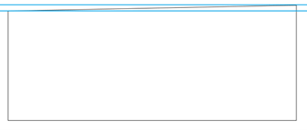
This means that the top side must be parallel to the bottom side within the limits of 0.1 mm to the distance between the two blue lines in the diagram below. Note: this is a grossly exaggerated sketch to clearly show the slope.
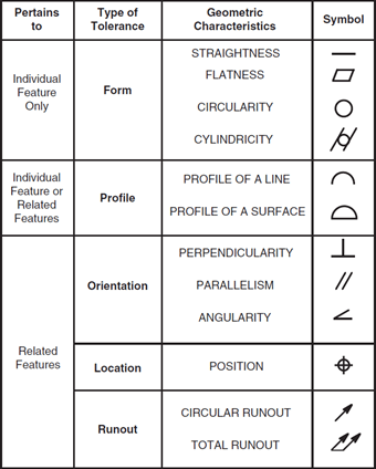
The example above is just one of the geometric characteristics in GD&T, in total there are 14 tolerances can be defined for. These are shown in the image below:
Tips for application of tolerances
There are six main reasons why it is important to always apply tolerances:
- Improved fit and functionality of the part: If multiple parts are going to be assembled, tolerancing ensures that they will fit and function well.
- Improved aesthetics of the product: To avoid obvious gaps between parts, or ensure two parts are flush when assembled, both parts' dimensions need to be controlled.
- Accounting for error: When defining tolerances from the start, it is less likely that parts will have to be remade.
- Manufacturing is more cost-effective: By tolerancing, a product will only be as precise as it needs to be. This way, only the materials, manufacturing tools, and labour this is needed will need to be paid for.
- Products get to market faster: Mismeasurements and inconsistent products increase time to market, tolerancing prevents this by clearly communicating all needed information.
- Reduced manufacturing ambiguity and complexity: If what is needed isn't specified, an unusable product may be produced. Tolerancing removes all ambiguity from the manufacturing process.
Should you add the tightest tolerances possible to every dimension? No. Generally, the tighter the tolerance the higher the cost. This is because it takes more time, skilled labour, and expensive machinery to create the product with a higher degree of precision and accuracy. The difficulty is deciding which tolerances matter most and how tight or loose those tolerances need to be.
While tolerances are important, it is just as important to apply them correctly. Below are some tips on how to do exactly that.
Keep tolerances as large as functionally possible
In general, tolerances of ±0.1 mm are expected and achieved from today's CNC mills. To provide some context, an average human hair is also around 0.1 mm in diameter. However, just because you can hold tolerances smaller than a human hair doesn't mean you need to.
The engineer or designer should strive to keep tolerances as large as possible while preserving the function of the part. Small tolerances can increase the cost of the manufacturing, inspection, and tooling of parts. Tight tolerances are sometimes necessary, but it's important to keep them in perspective.
Understand the manufacturing process being used
Different manufacturing processes require and can achieve different tolerances. For example, when manufacturing rubber parts, the moulding process is generally able to achieve higher tolerances than the extrusion process.
What Rubber Materials Should be Used? Different types of materials have differing levels of accuracy, consistency, and shrinkage rates. For example, it is significantly easier and cheaper to achieve tight tolerances for metal parts than achieving the same tight tolerances for rubber parts.
Be sure to consider how the part will be assembled
One of the most important considerations when applying tolerances is fit. This is how shafts fit into bearings or bushings, motors into pilot holes, and so on. Depending on your application, you might want a clearance fit to allow for expansion due to heat, a sliding fit for better positioning, or an interference fit for holding capability.
Be aware of tolerance stacking
This is when tolerances are based on points that have tolerances of their own, as described below.
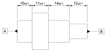
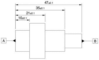
Although every length dimension has the same tolerance, the maximum tolerance between surfaces A and B can be as large as ±0.4 in the diagram above or as low as ±0.1 in the diagram below. This is due to the way the dimensions and tolerances have been specified.
Be careful when applying tolerances to radius or diameter
A radius’ tolerance will double when measured as a diameter, so if care is not taken, this may lead to tolerances that are looser or tighter than intended.
Rubber tolerances vs. metal tolerances
It is significantly easier and cheaper to achieve tight tolerances for metal parts than it is to achieve the same tight tolerances for rubber parts. Compare ISO 3302 with ISO 2768, which shows typical tolerances for machined metal parts.
| Nominal dimensions (mm) | E1, ± (mm) | E2, ± (mm) | E3, ± (mm) | |
|---|---|---|---|---|
| Above | Up to and including | |||
| 0 | 1.5 | 0.15 | 0.25 | 0.40 |
| 1.5 | 2.5 | 0.20 | 0.36 | 0.50 |
| 2.5 | 4.0 | 0.25 | 0.40 | 0.70 |
| 4.0 | 6.3 | 0.36 | 0.50 | 0.80 |
| 6.3 | 10 | 0.40 | 0.70 | 1.00 |
| 10 | 16 | 0.50 | 0.80 | 1.30 |
| 16 | 25 | 0.70 | 1.00 | 1.60 |
| 25 | 40 | 0.80 | 1.30 | 2.00 |
| 40 | 63 | 1.00 | 1.60 | 2.50 |
| 63 | 100 | 1.30 | 2.00 | 3.20 |
| 100 | - | 1.30% | 2.00% | 3.20% |
| Nominal dimensions (mm) | Tolerance class designation | ||||
|---|---|---|---|---|---|
| Above | Up to and including | f (fine), ± (mm) | m (medium), ± (mm) | c (course), ± (mm) | v (very course), ± (mm) |
| 0.5 | 3 | 0.05 | 0.10 | 0.20 | - |
| 3 | 6 | 0.05 | 0.10 | 0.30 | 0.50 |
| 6 | 30 | 0.10 | 0.20 | 0.50 | 1.00 |
| 30 | 120 | 0.15 | 0.30 | 0.80 | 1.50 |
| 120 | 400 | 0.20 | 0.50 | 1.20 | 2.50 |
| 400 | 1000 | 0.30 | 0.80 | 2.00 | 4.00 |
| 1000 | 2000 | 0.50 | 1.20 | 3.00 | 6.00 |
| 2000 | 4000 | - | 2.00 | 4.00 | 8.00 |
The four main reasons why rubber tolerances are so loose are:
- Rubber is a soft material: It is difficult to hold tighter tolerances on soft materials because the measuring method often causes deformation, which can significantly alter the measured value.
- Rubber is natural: Natural rubber is an organic material that comes from live trees; therefore, there can be material variances from batch to batch that will create relative tolerance variations.
- Rubber manufacturing process: Variations, such as rubber shrinkage or swelling, can occur during manufacturing, sometimes affecting the tolerances because they cannot always be predicted.
- Rubber is compounded: Other ingredients are added to the natural or synthetic rubber to help with the curing process, this mixture of added ingredients can affect the amount of swelling or shrinking.
Tolerances achieved at Walker Rubber
Here are the tolerances we adhere to in the tables below.
For rubber extrusions, we work to ISO 3302:
| Nominal dimensions (mm) | E1, ± (mm) | E2, ± (mm) | E3, ± (mm) | |
|---|---|---|---|---|
| Above | Up to and including | |||
| 0 | 1.5 | 0.15 | 0.25 | 0.40 |
| 1.5 | 2.5 | 0.20 | 0.36 | 0.50 |
| 2.5 | 4.0 | 0.25 | 0.40 | 0.70 |
| 4.0 | 6.3 | 0.36 | 0.50 | 0.80 |
| 6.3 | 10 | 0.40 | 0.70 | 1.00 |
| 10 | 16 | 0.50 | 0.80 | 1.30 |
| 16 | 25 | 0.70 | 1.00 | 1.60 |
| 25 | 40 | 0.80 | 1.30 | 2.00 |
| 40 | 63 | 1.00 | 1.60 | 2.50 |
| 63 | 100 | 1.30 | 2.00 | 3.20 |
| 100 | - | 1.30% | 2.00% | 3.20% |
When manufacturing rubber mouldings, we work to ISO 3302:
| Nominal dimension (mm) | M1, ± (mm) | M2, ± (mm) | M3, ± (mm) | M4, ± (mm) | |||||
|---|---|---|---|---|---|---|---|---|---|
| Over | Up to and including | F | C | F | C | F | C | F & C | |
| 0 | 4.0 | 0.08 | 0.10 | 0.10 | 0.15 | 0.25 | 0.40 | 0.50 | |
| 4.0 | 6.3 | 0.10 | 0.12 | 0.15 | 0.20 | 0.25 | 0.40 | 0.50 | |
| 6.3 | 10 | 0.10 | 0.15 | 0.20 | 0.20 | 0.30 | 0.50 | 0.70 | |
| 10 | 16 | 0.15 | 0.20 | 0.20 | 0.25 | 0.40 | 0.60 | 0.80 | |
| 16 | 25 | 0.20 | 0.20 | 0.25 | 0.35 | 0.50 | 0.80 | 1.00 | |
| 25 | 40 | 0.20 | 0.25 | 0.35 | 0.40 | 0.60 | 1.00 | 1.30 | |
| 40 | 63 | 0.25 | 0.35 | 0.40 | 0.50 | 0.80 | 1.30 | 1.60 | |
| 63 | 100 | 0.35 | 0.40 | 0.50 | 0.70 | 1.00 | 1.60 | 2.00 | |
| 10 | 160 | 0.40 | 0.50 | 0.70 | 0.80 | 1.30 | 2.00 | 2.50 | |
| 160 | - | 0.3% | 0.4% | 0.5% | 0.7% | 0.8% | 1.3% | 1.5% | |
For cut gaskets and other cut products, we are committed to the tolerances specified by the Rubber Manufacturers Association (RMA):
| Nominal dimension (mm) | C1, ± (mm) | C2, ± (mm) | C3, ± (mm) |
|---|---|---|---|
| For thicknesses up to 6mm | |||
| Under 25 | 0.60 | 0.80 | 1.00 |
| Over 25 up to and includig 160 | 0.80 | 1.00 | 1.25 |
| Over 160 | 0.60% | 1.00% | 1.60% |
| For thicknesses over 6mm and to 12mm | |||
| Under 25 | 0.80 | 1.00 | 1.25 |
| Over 25 up to and including 160 | 1.00 | 1.25 | 1.60 |
| Over 160 | 0.60% | 1.00% | 1.60% |
| For thicknesses over 6mm and to 12mm | |||
| Under 25 | 1.00 | 1.25 | 1.60 |
| Over 25 up to and including 160 | 1.25 | 1.60 | 2.00 |
| Over 160 | 0.60% | 1.00% | 1.60% |